RTL FIR Filter Detailed Description
This description is primarily of the RTL implementation of the
FIR filter used in this tutorial.
A Finite Impulse Response, or FIR filter is a digital filter
which produces an output out that is the weighted sum of
current and past inpute in as depicted below:

The filter contains some number of stages, in the case shown
above, 16, and each is fed with the input signal and a set
of constants which define the filter's response.
As mentioned in the main tutorial page, this FIR filter design is
implemented in both a behavioral style and in an RTL style of
coding. In the illustration above, there is an implication
that if this were defined in sequential code the resulting
hardware resource allocation would be:
- 16 multipliers
- 16 adders
- 16+ registers (noted d1 .. dn above)
- some glue logic
Depending upon constraints, it is possible that the behavioral
implementation of our FIR filter could be allocated as above,
or in any of several other allocations.
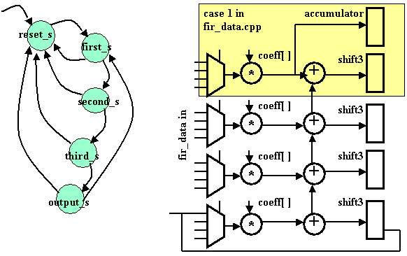
Our RTL implementation of the design is more economical of hardware
real estate than the one-for-one described above. In this
implementation we are explicitely specifying the FSM to
control the operations to use multiplexers, as the state diagram
and functional diagram of our design shows below:

Our design uses only:
- 4 multipliers
- 4 adders
- 4 shift registers
- 4 multiplexers
- 1 accumulator
- 1 state register (in main state machine in fir_fsm.cpp)
- some glue logic
The highlighted diagram section annotated "case 1 in fir_data.cpp"
above corresponds directly to the case 1 case statement in
the fir_data.cpp file. The remaining sections correspond to
case 2, 3, and 4 respectively.
State names of the state diagram appear in fir_fsm.cpp in the
main state machine section of the code.


