Computer Display Interface -- Implementation Details
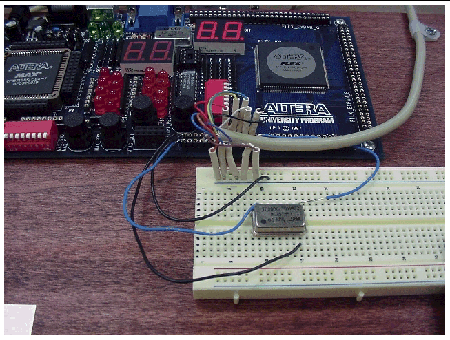
The following is the recommended interface connections to be made between the Altera UP 1 board, the external 16.3840 MHZ Oscillator, and the EGA monitor. Students who request help from the lab or course instructor must adhere to this wiring format Also if this format is followed then no buffering of the signals will be required.
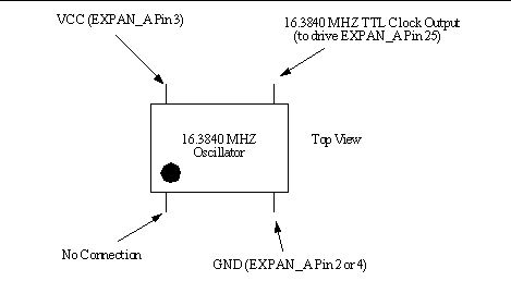
You are to use an external 16.3840 MHZ TTL oscillator IC to provide the base timing signal. The output of this oscillator is to drive one of the Altera 10K20 pins (Pin 25) that are connected to the EXPAN_A connector in the manner shown below.

