The estimated completion time for this tutorial is 2 to 3 hours. After you complete the tutorial, you are encouraged to take the following Synopsys classes to learn more about the SystemC language and SystemC Compiler:
Enter
unix% cp -r $SYNOPSYS/doc/syn/scc/ccsc_tutorial $HOME
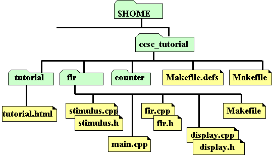
The ccsc_tutorial directory structure is similar to the following:

To access SOLD, enter
unix% $SYNOPSYS/sold
Refer to these manuals for more details about SystemC coding and SystemC Compiler commands. These manuals also contain other design examples that you can use.
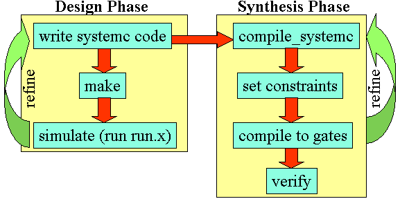
Good design practice does suggest that if your refinement changes involve changes to the source code, that you repeat simulation in the Design Phase before proceeding with Synthesis.
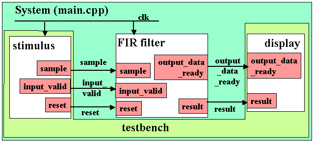
During the design phase, you create a SystemC circuit and a testbench, as illustrated in the following figure:
When you execute the make command to create the executable, the resulting file (here named run.x) can be executed and your testbench monitor (usually a print output) displays the results.
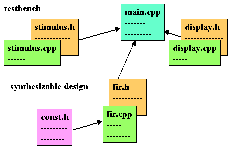
The inputs to the SystemC makefile for the behavioral version of this design are illustrated in the following figure:
The FIR filter design is implemented in both the behavioral coding style and RTL coding style. Each style has its advantages and disadvantages, some of which are explored in this tutorial.
A behavioral coding style is an algorithm or a pseudocode description. An RTL design is a structural implementation. SystemC Compiler can synthesis both behavioral and RTL designs into hardware.
The purpose of the first lab session is to familiarize you with the constituent parts of the behavioral version of this design and testbench, to run the simulation, and to walk through the steps of using SystemC Compiler under normal conditions. The second part explores the RTL version of this design.
For this first lab, follow the steps explicitly to understand the typical command flow before you experiment with alternate commands and options.
If you are not familiar with the operation of a FIR Filter or need detailed information regarding the SystemC model, see the fir description.
To compile the examples in this tutorial, you need to execute the make or gmake command at the UNIX prompt to compile and link the design.
Enter
unix% gmake -f Makefile.gcc
Notice there are several versions of the Makefile, one for each operating system (Solaris, HPUX, linux) for the behavioral fir filter design, and a similar set for the rtl version of the design. Use your favorite editor to view these if you wish. Also notice there is a README file, which describes the FIR filter and the design files. There are also a number of files with "rtl" in their name. These files are for the RTL version of this design for the second lab session.
The gmake command uses the default setting in the Makefile.defs file. It defines the location of the SystemC class library, which is probably in a different location for your installation. If you get errors, check the Makefile.def file and make the appropriate changes for your installation. For more information, see compiler requirements and environment variables, or check with your system administrator for help.
If you get errors, you can remove the previously generated
executable files by entering:
unix% gmake -f Makefile.gcc ultraclean
Then enter the gmake -f Makefile.gcc command again.
When gmake -f Makefile.gcc executes correctly, it generates the executable files, run.x, fir.x, and so forth in the current directory. To see these files, enter
unix% ls -a
Run the simulation by entering
unix% run.x
The simulation output shows the stimulus, the time it was applied, the display response, and the time it occurred. For example,
fir-behavioral version output
Stimuli : 0 at time 9
Display : 0 at time 10
Stimuli : 1 at time 19
Display : -6 at time 20
o
o
o
You will use this output later in the tutorial to compare the results of the behavioral and RTL synthesis.
SystemC Compiler is fully integrated with Design Compiler. The typical commands for synthesizing the design are shown in the following figure:

You invoke SystemC Compiler from within Design Compiler. Start the Design Compiler dc_shell by entering the following at a UNIX prompt:
unix% dc_shell
dc_shell> help compile_systemc
To display information about the bc_enable_analysis_info variable, enter
dc_shell> help bc_enable_analysis_info
To execute the behavioral command script, you would enter
dc_shell> include fir_beh.scr
Or from the UNIX shell prompt, you could invoke the script with
unix% dc_shell -f fir_beh.scr
Later, when you do the RTL portion of this tutorial you will use a script, but for the first time through with the behavioral design, it is useful to invoke the individual commands manually.
dc_shell> search_path = search_path + "$SYNOPSYS/libraries/syn"
dc_shell> target_library = {"tc6a_cbacore.db"};
dc_shell> synthetic_library = {"dw01.sldb","dw02.sldb"}
dc_shell> link_library = {"*"} + target_library + synthetic_library
dc_shell> bc_enable_analysis_info = "true"
dc_shell> compile_systemc fir.cpp
For a list of compile_systemc options, see the CoCentric SystemC Compiler Behavioral User's Guide or the compile_systemc man page.
You can write the initial output of the compile_systemc command as an elaborated database. Look at the fir_beh.scr script to see the syntax for the write command.
dc_shell> create_clock CLK -p 25
Other constraints are not necessary, but you might want to know how to instruct SystemC Compiler to not use certain libraries or implementations. You can use the set_dont_use command to
dc_shell> set_dont_use dw01.sldb/*/bk
dc_shell> set_dont_use dw01.sldb/*/csm
dc_shell> set_dont_use dw01.sldb/*/clf
dc_shell> set_dont_use dw01.sldb/*/rpl
dc_shell> bc_check_design
The bc_check_design command is optional, however, it checks for errors that could prevent your design from being scheduled. Because bc_time_design can take some time on larger designs, it is best to perform bc_check_design to catch syntax errors before timing the design.
dc_shell> bc_time_design
After the design is successfully timed, it is recommended that you save the timed database with the write command. At a later time you can read the timed database into SystemC Compiler to explore different scheduling possibilities.
dc_shell> schedule -io super -effort low
To learn more about scheduling modes, see the CoCentric SystemC Compiler Behavioral User Guide.
After scheduling the design, it is recommended you write the scheduled database with the write command. See the command syntax in the fir_beh.scr script.
dc_shell> report_schedule -sum > fir_beh.rpt
Note: To use BCView you must have set bc_enable_analysis_info = true prior to invoking the compile_systemc command.
To invoke BCView, the graphical design analysis tool, enter
dc_shell> bc_view
When you invoke bc_view, a set of windows similar following display:
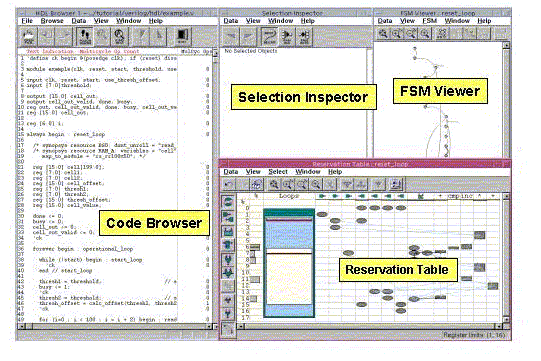
Use BCView to find design or constraint problems. If there is a problem with the basic design, you will need to make changes in the source code and run the compile_systemc command again. If your problems can be solved by changing scheduling or timing constraints, you can either edit your script or invoke the dc_shell commands at the command line and re-schedule.
BCView invokes with four or five windows. BCView displays the following windows:
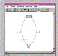 | The Scheduling Error Analyzer (SEA) window displays only if there are scheduling errors. It displays a beginning node in the FSM (shown at the top), an ending node in the FSM (shown at the bottom), and the path (transition) between these nodes that the scheduler was not able to schedule. The right-hand arc is annotated with the constraint that prevented scheduling. SEA also shows another path as an arc on the left-hand side, which is annotated with the minimum constraint value schedule you need to provide for this path in the FSM to schedule. |
| The Finite State Machine (FSM) Viewer derives its display from your behavioral source code after your design is scheduled. States in the state machine are shown as bubbles, and transitions from one state to another are shown as arcs. If you click a state, the code of that state is highlighted. You can then press the Tab key to execute the transition to the next state. If there is an alternate transition possible out of a state, pressing Ctrl-Tab takes the alternate path. |
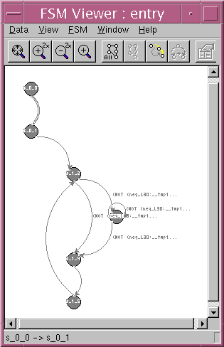
|
As the illustration below demonstrates, the Reservation Table Viewer displays a lot of information in a very compact format. The illustration below is not precisely the screen you will see when you run BCView against the fir design, it is an annotated example intended to explain the various windows of BCView.
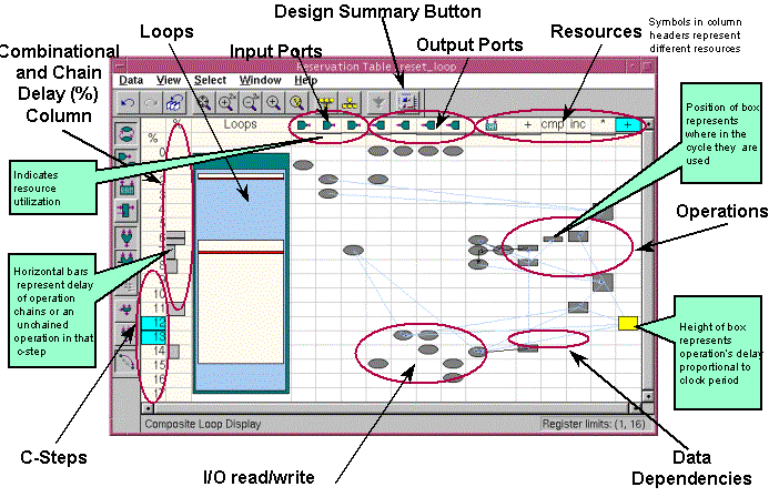
In the Reservation Table, you can observe whenever I/O ports are accessed, when operations span more than one clock cycle multicycle operations), what resources (adders, multipliers, and so forth) are used and when they are used in the design, how loops actually operate, the function of combinational and chain delayed operations, and the position within a clock cycle where an operation occurs. Details about these operations are explained in the CoCentric SystemC Compiler class.
dc_shell> bc_view
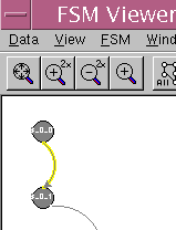
|
Notice that items in the Reservation Table highlight and the code section
corresponding to that transition selection in the Code Browser
is hightlighted. Click the Prev File Next File button to view the C/C++ file (shown by default), and click Prev File Next File again to see the header file. |
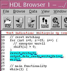
|
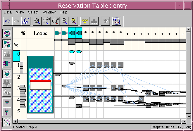
Due to your transition selection, output ports are highlighted. These correspond to the write statements highlighted in the code section. A full exploration and explanation of the capabilities of BCView is beyond the scope of this tutorial. You can, however, experiment with the cross-highlighting and observe how you can use the FSM Viewer and the Reservation Table to single-step through your design.
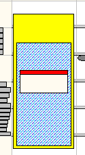
| Then in the Reservation Table, select the outer loop of the design. The Selection Inspector window will display the overall statistics about your design, including such items as scheduling, area, and timing. Notice that as you pass the cursor over elements in the Reservation Table (and in other windows as well) a pop-up "tip" message appears to identify the element in your design. |
|
dc_shell> compile
When compilation is complete, write out the gate database and create a timing report and area report. Enter
dc_shell> write -hier -f db -o fir_gate.db
dc_shell> report_timing > beh_timing.rpt
dc_shell> report_area > beh_area.rpt
When this is complete, you can exit from dc_shell.
dc_shell> exit
Read the timing and area reports to learn what the compile procedure produced.
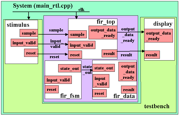
This hierarchical RTL design has a fir_top.cpp file that instantiates the fir_fsm state control module and a fir_data module. The fir_fsm is the finite state machine for the FIR filter, and the fir_data provides the coefficient set that replaces the coeff.h used in the behavioral FIR design.
The main_rtl.cpp file connects the fir_top to the stimulus and display modules through its ports and signals, similar to the behavioral model.
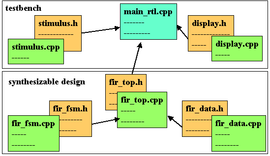
unix% gmake -f Makefile.rtl
When the gmake command executes correctly, it creates a new RTL executable, run_rtl.x.
Run the simulation by entering
unix% run_rtl.x
Compare the RTL simulation results to the behavioral simulation results you generated from running the run.x simulation.
Compare the output of the two model implementations. There are some differences between the two outputs. In the behavioral version there is a one "cycle" delay between input and output, whereas there is a three cycle delay in the RTL version. In the behavioral version, as soon as input data is complete, the model executes and places data at the output. In the RTL version, the state machine has a reset state that requires three cycles to execute, and three states must execute before the output occurs. Except for the differences in the number of cycles to execute, the output values match between the two models because they are functionally equivalent.
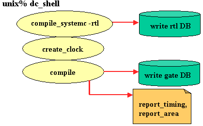
unix% dc_shell -f fir_rtl.scr
Looking at the fir_rtl.scr script, you will see the compile_systemc -rtl options available for RTL synthesis are different than those you use for behavioral synthesis. Architecture and scheduling constraints are all pre-defined in your code when you design using the RTL style. You can, however, use the Synopsys Design Analyzer tool to graphically view the results of your compile_systemc -rtl step. You can also invoke design_vision, setup a command window in Design Analyzer, and invoke compile_systemc -rtl within this environment.
Invoke the Synopsys Design Vision tool. Enter
unix% design_vision
If this is the first time you have invoked this tool, it will take a few moments to build registry information. When this is done, the Design Vision screen displays.
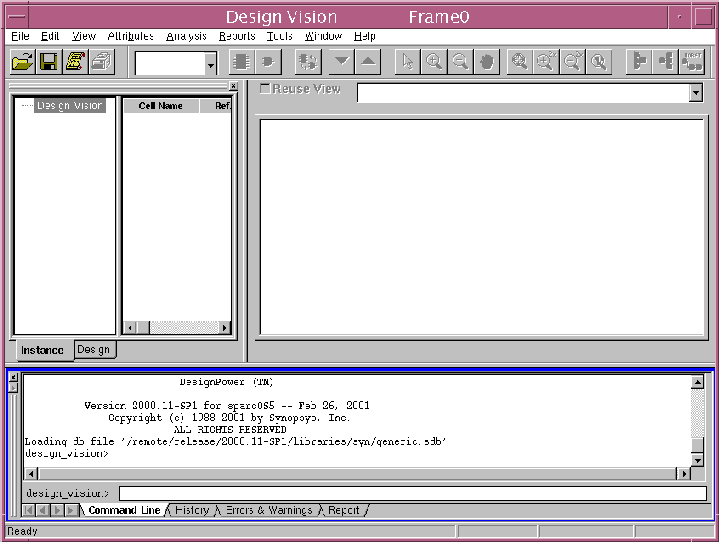
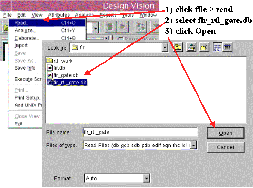
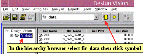
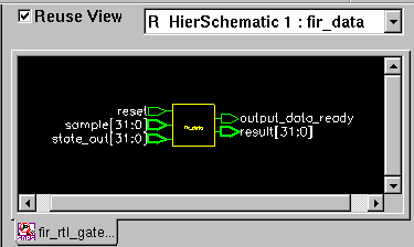
| In the Edit window the symbol of the RTL version of
the fir filter design appears. Select the symbol by clicking it in the Edit window. |
|
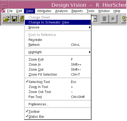
| In the View menu, select Change to Schematic View. Your generated schematic is displayed in the Edit window. |
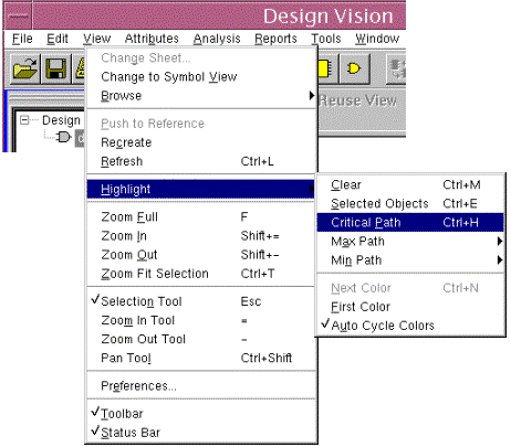
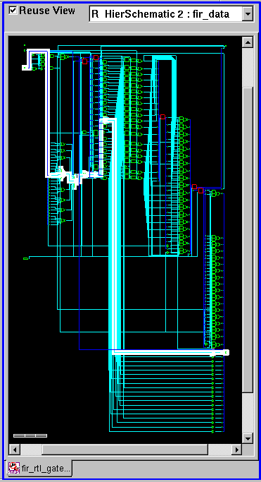
Repeat the steps you just performed to open the results of compilation of the behavioral design, which are contained in the fir_gate.db file. Notice the actual generated schematic is different, although when you inspect it, you will see that it is functionally the same.
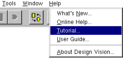
| There are many other features of Design Vision. If you want to learn more about Design Vision, select the Online Tutorial in the Help menu. |
You are now finished with this tutorial. You explored simple operation of the tools and looked at some of the design details.
The following is a bonus step you can perform:
This tutorial did not discuss issues such as:
Another topic not covered is communication protocols and how you can use them to separate the communication behavior of a module from its function. This allows easy retargeting of a design to different platforms. SystemC provides multi-level communications semantics so you can describe your system and module communication interface at the data transaction level, the bus-cycle level, or the clock-cycle level. This provides you with the level of abstraction you need to model your system.
Finally, you can configure your design for and FPGA implementation, too. This tutorial demonstrates the usage of the tool through the ASIC flow, but with one simple additional command, set_fpga properly placed in your dc_shell command script, you can target an FPGA device. This, and many other topics are covered in the classes discussed below.
North America Workshops
Additionally, classes about the SystemC language are available from
Willamette HDL
. SystemC classes are also provided by other companies in many countries, which are listed in the
SystemC Open Community
web site.
Israel
Munich
United Kingdom
Other European Countries
Taiwan
Other Asia Pacific Countries